Saturday, January 31, 2009

ACME threaded rod.

I bought it from

Bomond Trading Co Pty Ltd
49 Orchard Rd, Brookvale, NSW 2100
p: (02) 99391344


1/2 inch (12.7mm) ACME threaded rod (aka leadscrew), 10 tpi (10 turns per inch). This is rolled rather than ground so it's less accurate.

The chap at Bomond was very helpful; I phone up on thursday, he said it was a speciality item, but he could get next day. I went this on saturday (this morning), and picked it up. The length of leadscrew and a handful of M10 nuts was under $AUD100 so I was pretty happy. It was the closet place in Sydney I could find to supply it. There's a number of other places I'd found, but they were a long drive away.

The only fly in the ointment was that I was expecting it to be a 3 meter length, but it was actually 12 foot. For some mad reason I'd heard "12 foot" and mentally translated that to "about 3 meters". Of course, it's actually about 3.7 meters, which is longer than will fit in the car.

Bomond didn't have cutting facilities, but I was on my way to Edcon Steel to pick up some aluminium flat bar, so I just left it poking out of the boot of the car a bit while I drove around the corner and asked the chap at Edcon to snip 1150mm off one end for me. Nice and easy.

Wednesday, January 28, 2009

Stepper motors

The stepper motors I have are Linengineering 4118S-62-07 motors. They were a surplus item, so unfortunately the datasheet doesn't seem to be a very common.

My motors are rated for 2.5A per phase, and a resistance of ~1 ohm is cited in a catalogue with a ~3.6Kg-cm torque.

Looking at http://www.linengineering.com/site/products/4118.html and extrapolating a bit, my motor would be something like the 4118S-04V, or having approx the same torque the 4118S-04P does, just at twice the rpm.

So when I'm running my mill at 2000mm/sec on a 1.25mm pitch, that's about 26 revs/sec. Which would be something like 1600g-cm of torque from my wild guessing and eyeballing the graph. Which, frankly, isn't too bad at all at all!

If I get this ACME at 10tpi (or 2.54mm pitch), I should be able to run a similar speed, but at 13 revs/sec and ~ 2200g-cm of torque. When is very reasonable indeed. Ok, I'm sold.

Now I'm off to buy some 3 meters of ACME threaded rod.

Tuesday, January 27, 2009

Simple image to g-code converter


I did a tiny little bit of tidy up and uploaded my trivial C program to http://code.google.com/p/imagecarve/

The program simply translates images to G-code. It does nothing else. It assumes that you're capable of editing the resulting G-code to make it usable on your machine, and that you can add minor things to the g-code like feed rates et al.

It's pretty raw. It assumes many things, including that you have a ballnose cutter and that the input is always correctly formatted PGM.

The line I used to generate the (upside down) image from the pic above is:

cat ../IMG_545.JPG | jpegtopnm | ppmtopgm |
./imagecarve --scale=0.25 --toolsize=3.2 --stepover=1.5 > out.g

followed by hand editing of the resulting 'out.g' file to set a feed rate.

Monday, January 26, 2009

Yay! First cut!


After a lot of preperation the mini-mill is cutting foam again! Pic shows a little test cut from semi hand-rolled G-code. It was done with a 3.2mm ball-nose endmill, using a 2mm stepover and running at ~ 400mm/minute feed rate.

Frankly, the biggest thing it showed was that I feel the need for speed! It could easily have cut at > 1000mm/minute given the fairly shallow cuts being taken. My steppers are pretty tiny, and the threaded rod I'm using is only a 1.25mm pitch so it's spinning pretty fast to reach the 600mm/min rapids it's currently doing. I think I see a purchase of some ACME threaded rod in my future... Which will mean re-doing all the delrin nuts again, dammit.

Currently debating if I should buy 1/2inch or 5/8th inch rod (~12mm and ~16mm respectively). The 12mm is 2.54mm pitch, and the 16mm is 4.3mm pitch, so the 5/8th is capable of much higher speeds, at the cost of some accuracy and backlash. Still very undecided on this.

I say 'semi hand-rolled' G-code as it involved initially a significant chunk of perl, and eventually a chunk of C code that properly compensated for the cutter size. At the moment, it will take a PGM image and convert it into G-code, treating the grey levels as a high map. It's did a semi-reasonable job of carving a picture of K into foam; albeit with some oddities given the simple lightlevel->height conversion. Took nearly an hour to carve a 120mm x 80mm image tho. I am seriously feeling the need for speed!

Sunday, January 25, 2009

Getting slower better at milling.


I'm slowly getting better at maching parts. The photo is a trival couple of spacers; Just some aluminium box, cut and faced to the same length.

I cut them on the bandsaw, squared one end of each on the mill, turned them over, stood them on equal bars and then run a face cutter over the pair.

Pretty trivial machining, but it still involved 3 tools. The nice bit that I'm happy about is that it only took me about 5 to 10 minutes. I'm very slowly getting more experienced and quicker.

This morning I was making more delrin nuts (for the mini-mill) and had both the lathe and knee-mill running at the same time. The lathe was on auto-feed facing and then parting delrin, while the mill was on power-feed facing the aluminium bracket. Less standing around waiting while the machines take fine cuts. Not entirely sure it was a good idea, but it did make things go faster.


The PCBs for the relay board finally arrived from BatchPCB. (Well, I should say I finally got them; Turns out they were sitting the mailroom at work waiting for me to pick them up for about 2 weeks. Oops)

Pic is a raw board on the right, and a fully assembled board on the left. The board went together fairly easily.

I tried to use the SMD oven for the first time in anger, and was mildly annoyed to find that it doesn't quite reach the melting point of the lead-free solder I'm now using. Dammit. I need to get a toaster oven or similar.

So I just hot-air soldered all the SMD components, and then hand-soldered all the through hole components. A lot of soldering! Took most of an hour to solder it. ( Some 123 thru-hole solder points).

Interestingly, I managed to get a dry-solder on one of the SMD components. I suspect I managed to just not put enough solder paste on it, but it's a first for me. I fixed it by hand-soldering; Good thing it was an enormous 0.8mm pitch component.

Board is now plugged into an ATNGW100 and it looks like it's working well. I can read temperature from a DS18B20+ that's attached to one of the 1-wire interfaces, and the board hasn't caught fire. Yay!!

When I get time later today I'll do the spot of programming to talk to the GPIO pins and start testing the relay drivers, RS422, and SPI interfaces.

Eye-Fi, grumble, grumble.

The Eye-Fi card simply stopped working a few days ago.

After trying the usual sorts of things (power cycle, power cycle again in a fit of sheer optimism, opwer cycle with it next to the access point, tcpdump on the network looking for it's MAC address) it was clear that things had gone badly wrong.


10:38:04.919893 00:18:56:10:1d:b6 > Broadcast, 802.3, length 60: LLC, dsap Null (0x00) Individual, ssap Null (0x00) Response, ctrl 0xaf: Unnumbered, xid, Flags [Response], length 46: 01 00
10:38:09.174952 00:18:56:10:1d:b6 > Broadcast, 802.3, length 60: LLC, dsap Null (0x00) Individual, ssap Null (0x00) Response, ctrl 0xaf: Unnumbered, xid, Flags [Response], length 46: 01 00
10:38:13.444594 00:18:56:10:1d:b6 > Broadcast, 802.3, length 60: LLC, dsap Null (0x00) Individual, ssap Null (0x00) Response, ctrl 0xaf: Unnumbered, xid, Flags [Response], length 46: 01 00
10:38:17.707051 00:18:56:10:1d:b6 > Broadcast, 802.3, length 60: LLC, dsap Null (0x00) Individual, ssap Null (0x00) Response, ctrl 0xaf: Unnumbered, xid, Flags [Response], length 46: 01 00


It was basically just broadcasting an invalid ethernet frame over and over again. Curses. Looks like it had corrupted its configuration.

After laboriously re-installing the windows software, it wanted a firmware update (2.0396 -> 2.0400 ) which I did. Pulling the log from the card showed things like..


[111:32] Disconnected from WLAN (reason = 4).
[111:32] Connection dropped (previous state is 2)


looping. Yuck. No idea what causes it to corrupt it's settings. It's "fixed" now in the sense that it's uploading images again, but I'm a little perturbed. (Luckily the firmware update didn't break the perl server).

I need to find out why Dave Hansens linux utility doesn't work and fix it. It's very annoying having to fire up a windows instance all the time.

Saturday, January 24, 2009

Bracket to suit.

This is the bracket that goes with the acetal nut. It's just a piece of 50mm x 50mm x 10mm aluminum, squared up on the mill, slotted with a 6mm end-mill, drilled in the center with same, increased out to 16mm with a 16mm roughing endmill, and then bored out to ~21mm with the boring tool.


The finished piece. I just love the finish the boring tool puts on holes. The final pass was cutting ~0.1mm deep, feeding at about 0.03mm per turn, so it was taking a pretty fine cut indeed. The result is this mirror smooth finish. Total overkill for this piece, but I take any opportunity to practise. The results I'm getting these days are far improved over the mess I made with it when I first got it.


Acetal nut fitted to bracket. The bolts are just my usual M6 stainless steel. There's about 5mm of adjustment available in both the X and Y directions.


The driving side. The nut isn't actually totally flat on this side. It turns out the parting tool I used to cut it off the bar isn't totally straight, so there's ~0.07mm of curvature across the nut. Which turned out to be fine as it's the otherside that fits to the bracket, but it's still annoying. Will have to get out the dial indicator and straighten the parting tool at some point; Come to think of it, I'd better do it soon before I forget and attempt to use a bent parting tool to part steel....

This bracket is fitted to the table mill and working very well. Much better than the old nut. Unsuprisingly, having the threaded hole accurate makes a big difference to the effort required to drive it. The tiny steppers I have easily drive it at better than 1200 rpm now.

Tuesday, January 20, 2009

My blogging process.

I'm not 100% happy with this, but it's still the least effort I know of.

I take photos with the Canon 20D, which then uses an eye-fi to upload to the server. The script on the server auto-sorts into directories by month.

I then use picassa on the linux desktop to pick out suitable photos, occasionally cropping particularly dud ones that I still want. After getting a few useful pics, I click on 'Blog this', and then 'Save as draft'. (As the picassa blog editor is awful).

Then I got to blogger.com, click on 'Edit posts', select the draft and add text. Then publish if all goes well.

Things that suck:

1. Picassa on linux frequently forgets to scan the directories regularly. I need to go to the Folder manager, change nothing, click OK, and then it finally scans the directory and picks up the new images.

2. Picassa won't 'Blog this' with more than 4 pics. Sometimes this is a pain.

3. There's no easy way to add captions to pictures that show up in the blog post. Picassa lets you set captions on pictures, but promptly discards them when you ask it to generate HTML. I kinda get the impression that 'Blog this' was a kinda half-arsed feature.

4. The Blogger editor is pretty flakey. Then editing posts that have images floated right, it's easy to get into a state when it simply won't add text at the top of the post. Increasingly, I just edit the HTML as it's easier than fighting the editor.

5. The whole process is still a large work burden than I'd like. My mental barriers to regularly updating the blog are high enough without fighting tools as well.

What do other people use?

TechCrunch tablet lappad

Looks like someone is finally building my ideal tablet.

http://www.techcrunch.com/2009/01/19/techcrunch-tablet-update-prototype-b

Reasonable price point, nice and simple, good sized screen, runs linux: What's not to like?

I'm still hunting something like this as a better interface for the home automation system.

Sunday, January 18, 2009

Finishing flanged nut


This is just finishing off the delrin nut for the table mill. After turning the blank on the lathe, I finished it off on the mill. This was basically just cut the top and bottom off to reduce the height to 30mm, then mill the slots either side (which will be used for position adjustment).


Acetal is seriously nice to work with. It cuts very cool (no lubricant or cooling required!), and the surface finish is just fantastic.

The only (very minor) downside is that it compresses slightly under load, so I needed to do a few passes on the slots to get them the right side.


Easy machine, relatively cheap (cost me ~$50AUD for a 1000m x 50mm rod), nice finish, tough. What's not to like!? :)

Acetal on the lathe


I started turning up the flanged nut for the X axis on the table mill. The current nut is made of UHMWPE (aka a piece of plastic cutting board), but it was made on a drill press, and it's accuracy is low enough that it binds fairly easily.

The new nut is made of Delrin (aka Acetal). This is my first time maching acetal and overall it was very pleasant. The only negative is that is grabs very easily. I got a little carried away and the autofeed was a little fast, and thus the piece of 50mm rod made contact with the ceiling. Oops.

Taking slightly lighter cut made everything good. The plastic machines to a very nice finish, and appears to hold it's shape very well. I just faced the rod, did a skim cut to true it, narrowed one section and then cut it off with a parting tool. Very easy!

I'll definitely be using this more.

The other thing I did was something I've been been meaning to do for a while. After tapping a thread into a hole, there's frequently small shards of metal et al which are difficult to remove. Just running a bolt into the hole tends to mash the splinters into the thread making a bit of a mess.

So took a normal M6 bolt, and used the ginder to put a groove up the side of it (cutting across the threads). Screwing this into the hole nicely removes the splinters of metal (they collect in the groove). This is akin to just running the tap in, but the bolt is a looser fit, and doesn't risk further cutting of the thread. Worked better than I expected.

Saturday, January 17, 2009

Home Switches


Today I added home switches to the table mill.

The microswitches were just ones I had lying around that were a suitable size. It didn't take long to discover that they mounted via a pair of 2mm holes. Unfortunately, I didn't have any M2 bolts around.

So with desperation driving necessity, I found a length of thick wire (actually ~ 1.9mm music wire) and used the drill to run it through an M2 die. This nicely gave me a length of M2 threaded rod.

In the spirit of hackery, I then drilled a pair of 1.5mm holes into the aluminium bracket, and use the drill to drive the threaded rod into the holes. The music wire being much harder than the aluminium, it just tapped a thread into the al bracket. Ta-dah! Easy mounting for the micro-switches. A very small bad of CA glue to stop things vibrating free and it's all done.

I'm still using MACH3 to drive the mill at the moment (haven't yet installed EMC2) but it's still neat to click on 'Ref All Home', and watch the mill drive the Z, Y and X axis to the home switches, stop, and reverse slowly until it comes off the switch.

I think tomorrow I'll be in shape to do the initial cuts on the upgraded mill.

Thursday, January 15, 2009

Eye

The range of the Eye-fi card is pretty ordinary indeed.

It can do 2 meters of air.
It can do 5 meters of air.
It can't do 10 meters of air + 2 glass windows.
It can't do 5 meters and a brick wall.

Am mildly disappointed. The last thing left to try is bump up the access-point power from 40mW to 250mW. This doesn't help if it's a transmit problem on the eye-fi card, but hey! it's about 50/50 right? right? :)

Wednesday, January 14, 2009

Actual progress


I basically finished re-assembling the table mill. Starting to look like it can actually cut something!

The table went on very easily. There's a lot of socket screws involved, so I took an old allen key and cut the tail off with the grinder. (With a stupid moment along the way; I had assumed the key would be case hardened as it's a cheap key, so I ground off the surface and then put it against the metal bandsaw. Mistake. Now I think I need to fit a new blade to the bandsaw. Doh! Not a total disaster as the blade was pretty close to the end anyway but still annoying)

The resulting hardened hex bar fits into the cordless drill and making doing and undoing socket screws very fast and easy.

I still need to finish aligning the table (need to get the electronics back together for that). I also finished all the plywood sections for the dust box.

Next step is to cut to the perspex lid and side for it, and hinge them on. Cutting the perspex will be .. interesting. It's only 3mm thick, but I need to make a greater than 1.5 meter long cut.

I'm planning on using the circular saw for it. I'll need to ensure that the perspex is clamped well on both side of the cut. Not going to be easy as I'm running a cut up the middle of a 2.4 meter long sheet. I suspect it will be a matter of reducing the depth on the circular saw to a minimum, using backing plywood, and lots and lots of weight. Not sure how else I can usefully clamp it.

Tuesday, January 13, 2009

Plastic fantastic


More toys arrived yesterday. This is 2 x 1000mm x 50mm Delrin rod. A fairly tough plastic, dimensionally pretty stable, and very, very easy to machine.

I bought it originally to make anti-backlash nuts, but I suspect it'll find up getting used for a fair few more things than that..

I'm planning to fire up the lathe this evening and turn a couple of nuts for the mini table mill, just to get some experience with the material.

Small progress


The original task to 'just remove a bit of lash' from the table mill has grown. A little. Just slightly.

So after adding the extra linear bearing, and noticing that the table structs needed fixing, which resulted in noticing that the drill holes in the original brackets weren't accurately aligned and basically tearing down the full X axis to do these things, I was on track to re-assemble.

Except that the side project of enclosing the mill (to contain dust and reduce noise) reared it's head and pointed out that it's much easier to add that while the mill is mostly disassembled.

Which led to noticing that the enclosure would shade the ethernet and power points on that side of the bench. So off to add extension leads to all power points and longer ethernet cables to ensure I wouldn't need to regularly get to them. Which led to relocating the PC to free up the desk space. And moving the monitor/keyboard. Which led to re-doing the power cabling to tidy it up a bit.

And so this evening I finally put two sides of the enclosure is on. I just used some angle aluminium to make brackets, and screwed the plywood on. Yay! Progress!

Except that in doing that and moving the X carriage around, I noticed that the nut wasn't quite aligned with the threaded rod...

On the bright side, it was an opportunity to use one of the most brutal tools I own: A 26mm , high helix milling bit. When you want to make a big hole in a hurry, and you're not too fussed about the accuracy, that's the way to do it!

A 26mm hole in 12mm aluminium, 8 seconds. Done! Sometimes, using a bigger hammer is just plain fun.

Monday, January 12, 2009

Timing belts


Another step toward finishing the CNC of the big mill arrived today. These are timing belts and pulleys. The largest one is ~300mm in diameter. I'll use this to run the Z-axis (aka the knee) on the mill, and the smaller ones to run a 2:1 reduction for the X and Y axis.

Like most solutions, they come with a problem. The holes are just guide holes, I'll need to bore them out to size. That's easy. The hard bit is cutting a keyway in each one. I don't have a keyway broach, and don't feel like spending ~ $200 just for this. I'll probably try and grind out out of a bit of high speed steel. We'll see how well that works....

I'm making slow progress on putting the table for the table router back together, but I've gotten mildly distracted by cleaning up the workshop.

The need to put a dust case around the table router has stirred up areas of the workbench that haven't been touched in months. So now I'm moving the PC under the bench, re-running the ethernet and power cables, tidying up and putting away, and generally making ~ 2 meters of bench space useable again. The long slow cycle continues!

Sunday, January 11, 2009

Tedious machining


Sorry, more machining. I'm still on my quest to rebuild/improve the mini table router.

The previous table supports were hacked together from a bunch of aluminium box, drilled and bolted at one end. It wasn't fastened at the other end, and the structs were overlength (I had never cut them to the right size). The ho

Today I drilled and tapped holes into both end brackets for the table support structs to bolt onto. This was drilling 14 holes, each 5 mm diameter, 35 mm deep, and then tapping said holes. Suprisingly, the bulk of the time went into drilling the holes. I suspect all my 5mm drill bits are getting blunt (I use 6mm bolts almost everywhere) so it may be time to invest in a drill sharpening tool. It took almost half an hour to drill the 14 holes. Part of the time was fiddly adjustment (release table clamps, wind table to x+70mm, fiddle back and forth until it was exact on the DRO, clamp table) but it just wasn't cutting very fast either. I get bored and wound up using the quill auto-feed and auto-stop to do the bulk of them.

The tapping by comparison went very fast. I love the VFD I fitted to the mill. It's just so nice to dial up 40 rpm, and let the tap just thread straight in. I press reverse when it's in far enough, and the VFS nicely slows the mill to a stop, and then winds it up into reverse. Makes tapping (at least in Al) very quick.

I followed this lot of tediousness by milling slots into the ends of all the table structs too. 28 slots (12mm slots on top, 6mm slots on bottom). Man, I'm glad I don't do this for a living.

Saturday, January 10, 2009

Boring


I had noticed earlier that there was a little too much slop in the mini table router. The Y-axis was rotating, being insufficiently restrained by the Z-axis carriage.

So this afternoon I got around to doing something about it (or maybe it was just an excuse for some boring action.. :)

I decided to add another pair of linear bearings to the top of the Z carriage so that a moment about the Y-axis would be carried by the bearings on the same rail instead of working to seperate the rails. This should (with a little pre-load) be much stiffer.

And while I had the boring set out, I enlarged the motor mount opening. The top photo is the boring bar in action, on autofeed. I love the finish it leaves! This is using a carbine tipped bar in aluminium which isn't ideal, but it was the bar I had to hand.

Nest was making a bracket for the linear bearings. This is a simple piece with 2 x 22mm holes for the linear bearings, and 2 x 7mm holes for attaching it (and 1 x 6mm holes in the center for the threaded rod to pass through). The digital readout on the mill makes this a piece of cake: Just touch off the piece to find the corner, set it to (0,0) on the DRO, then just drill 6mm pilot holes for the 2 x 22mm, enlarge to 16mm using a roughing mill bit, then use the boring bar to enlarge 1mm at a time to 21.8mm, then enlarge 0.0.05mm at a time to get to 21.99 which leaves the linear bearings a press fit.

Last photo in the new bracket installed. It's the top bracket on the Z carriage (the carriage on the vertical rails). There's a little preload from the Y rails, so it's now nice and stiff. Well, not up to cutting metal stiff, but it should now be adequate for wood and plexiglass. (I'd previously just used it for XPP foam and wax).

Friday, January 9, 2009

Modifying ACME nut on mill.


Taking another step toward converting my mill to CNC control, I decided this to take a closer look at the nut on the X axis with a view to seeing how easy it would be to replace/augment. (The idea being to remove backlash out of the system).


This is a little trickier than it would normally be because my mill has an X-Y digital readout, with the optical encoders bolted to the mill. These needed to be removed as the table was being moved beyond the normal limits to expose the nut.


Being an idiot, I look at the end with the power feed and said "Hmm. Looks complicated, let's leave that alone".


So I started with this end. After about 30 minutes of mucking around, it become abundantly clear that this was the end with the thrust bearings; I.e. the complex end. The end that's relatively high precision. And with the benefit of hindsight, it was obvious that the power feed would be fitted to the end that's easiest to fit to. Doh.


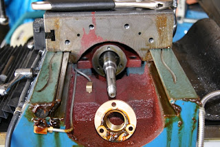
So back to the powerfeed end, it disassembled much more easily. This is after removing the retaining nut, handle, and feed cog. Nice simple mechanism.


The power feed just sits on roller bearing (no thrust bearing required) and so is very easy to remove after clearing the keyway.


And there's the acme nut. Piece of cake. Interestingly, it turns out there's two of them (another on the other side), so removing the backlash looks very easy. Just mill some slots in the nut, and turn it to adjust the degree of slop.


Nut removed.


Preparing to mill the nut. It's just centered and clamped onto a small rotary table. I'm using a 4 flute 6mm bit. The slots will be 7mm wide, but I didn't have a 7mm to hand, and I can just cut one side of the slot at a time.


All done. The slots I left slightly under size to improve the centering. It was the work of moments to reassembled everything and measure the nut backlash. (Well, many, many moments. About an hour actually).

Poor control


So I've been collecting data from the temperature monitors for a while now and one thing is abundantly clear.

The air-conditioning controller sucks.

(That would be HVAC for the crazy people that still haven't gone metric yet)

Graph is of room temperature for 4 rooms over the last 24 hours, with the air-conditioner turned on at ~ 1930. Note that it starts cycling almost immediately.

To put it in context, this is an AC that has a variable-speed-drive on the compressor, so there's no reason whatsoever that it should be oscillating. The PID loop driving it (and I do hope there is a PID loop...) should hold it all at a steady state.

(Note that the green line aka Living Room zone was turned off until ~ 2330 which is why it didn't start cycling until then. And the reason that the study isn't cycling more is that the balancing is awful and there's not enough air going to the study. Something I need to climb into the roof space to adjust the dampers for I think.

The AC is a Daikin FDYQ200MR. Which is a 22.2KW system I think. (Note that that's not the power draw: That's the peak heat-pumping capability).

Added to the to-do list: See if I can find datasheets for the AC VFD + compressor + evaporator, and scrap the existing controller in favour of talking to the VFD directly. Task #5412345 I think that is...

Thursday, January 8, 2009

Echo


The main living room in our house has always been a little harsh to my ear; I've been complaining to the wife that there's just too many hard surfaces in the room (lots of windows) which make it very 'bright' acoustically. This has the big down sides of making it difficult to understand what people are saying on the other side of the room, and annoying the hell out of me which the kids start making a racket.

So when D poked me on the subject this evening, it motivated me to go measure the problem. Mostly in a half-arsed sort of way to start with.

I used a crappy USB webcam which happened to have an in-built microphone to record audio, and then a tiny bit of perl to play a 1 KHz pulse out of the TV speakers at reasonably high volume. (Just a single cycle of a 1 Khz sine wave).

There are so many things wrong with this as a measurement setup it's difficult to count them all (not a pure tone, speaker distortion, awful directional microphone, no calibration to speak of, etc, etc, etc) but it was to at least give me an indication that it was worth putting more effort into it.

The graph above is the result. X axis is in seconds. It's rather entertaining that there's still significant energy in echos at 250 ms past the impulse. So it's not just all in my head: The room really is very echoy. Which I already knew, but now I has some numbers! Which is surely most of the way to fixing the problem, right?

Unfortunately, reducing echo is probably going to be non-trivial. At least, it will be given that D's hard requirement is that I don't cover the windows in felt...

We'll start with simple things like throw rugs over the couches, a tablecloth over the dining table, felting the undersize of the table and the bench. And if all else fails, the dreaded curtains discussion will probably enter the stage.

But first I need to get a better microphone. And some sort of software that's able to effectively measure and display how much the echo has changed. And maybe a good psychoaccoustic model. And a pony!

Wednesday, January 7, 2009

It's nice to be home...

Being away with family in entertaining, but there's something very nice about being home.

Today I have:
  • Kicked off PicardTagger to fix up all the tags on my various MP3 files. Free hint: If you have 26,000 mp3 files, don't try and feed them all at once into Picard. Looks like there's at least some O(n log n) algorithms in there, if not O(n^2).
  • Much hacking with Eye-Fi. It nows properly with the main linux server.
  • Rebuild an N800 device as a video-player for Katie. This is notable hindsight: It would have been better to do this before the 4 hour plane flight... Firmware is upgraded, video transcoder tools are installed and running. I ordered a new 8G flash micro sd-card to hold the videos.
  • Start more actively hunting down a dehumidifier for the garage. I'm tired of fighting the rust battle on the milling machine and lathe; I'll cheat by just dropping the humidity. Right now, it's often in the 80% range which is deadly to precision iron. EBay sniper is fired up and ready!
  • Fixed the bluetooth download for D's phone. The script that auto-detected D's phone as being in range and then grabbing all the pictures on it via bluetooth was broken by the semi-recent OS upgrade (forgot to cover up a config file). Each fix, but I still need to add some monitoring for it.
  • Had a long chat with Andrew B about planes,rockets and software. He kindly brought over the paint needed for my glider, so that's a repair I'll kick off on friday.
  • Polished off PID software for SMD oven. I left the hill-climbing running while we were away, so now I have the PID constants tuned to better than 6 significant figures. (NOTE: This is a total waste of time! This was running against the simulator, not the real hardware. But it's still entertaining). I had intended to use it in anger today, but ran out of time. The boards for the 200W audio amplifier are on the bench, I just need to heat them.
  • Gone for a swim with the kids. The long days make it very pleasant to go swimming at circa 7pm at night. I'm still waiting for the relay PCB boards to arrive from batchpcb.com but I have patience. Maybe. I hear Olimex calling my name.
  • Ordered the timing belts and pulleys for the mill CNC conversion. I'd decided that I'm just going to do it and the cost isn't that outragous. At least, not in comparison to some of the other things I've wasted money on over the years.
It's nice to be home. :)

Eye-Fi

Update: Perl standalone server that runs under linux for Eye-Fi card is linked here.

I bought an Eye-Fi sd-card a few weeks ago in a fit of laziness. The idea being I could put it in the SLR camera, and it would auto-upload images to the fileserver instead of me having to do the (very onerous..) walk to the server and plug it in.

I bought it in ignorance of the hugely proprietary nature of the card; Not sure I would have bought it knowing what I know now.

Part of the problem is that Eye-Fi's business model apparently includes charging large sums of money for trivial features. Thus, they go through all sorts of contortions to avoid you implementing said trivial features yourself rather than paying them.

Luckily, the protocol that the card uses on the WiFi side has been reverse engineered by others that have gone before me.

Chris helpfully wrote a little perl server that looked like it worked once apon a time. It appears that Eye-Fi have changed a few things since then so it took a little bashing to get it to work seamlessly with my card.

The two major changes are the certification calculation and the transfer mode.

It turns out that a different forumula is used to authenticate the client to the server. It's md5(mac addr, upload key, snonce) rather than the md5(mac address, cnonce, upload key) used in the other direction. Seems strange to me; Not sure this isn't a bug in the Eye-Fi code.

The other one is reflecting back the transfermode and transfermodetimestamp used in the session setup. Without this, the Eye-Fi refused to transfer more than one picture in a session.

Some minor changes include the server doing a fork for each client connect, and an unsuccessful attempt to verify that file checksum. The eye-fi card passes an MD5 sum along with the file on each upload, but it isn't a straight md5 of the tar file, nor of the embedded JPG file. I had a very quick poke, but the calculation wasn't immediately obvious to me so I wrote it off as a 'nice to have'.

Changed file can be found here. The upload key that's required in the file is stored in Settings.xml if you've used the windows app manager to configure the card. (Which I did: I failed to get it to do anything useful when run under wine).

So now I have it all working on my linux fileserver; When the camera comes into range and it's turned on, photos are automagically dropped into a spool directory, and a little daemon renames them into timestamped directories. So now I'm happy. Yay. :)

Ps: I would really have liked to get working the eyefi-config tools that Dave Hansen wrote but I simply couldn't get them to do anything beyond detect that there was a card in the USB adaptor. It appears that the protocol between the manager and the card has changed enough that the tools no longer work.

I had a quick bash trying to get the manager to run under wine so I could spy on the protocol, but after more than an hour of fighting wine the end wasn't in sight, so I moved onto other things.

IP Camera.

In my ongoing frustration to find a relatively cheap, IP based camera, I started looking at the Sparkfun 1300x1040 CMOS Camera. This is a $USD10 device, that connects via an 8-bit bus to ... something. In my case, that would be an ATNGW100.

I'll probably have to make up a board for it, to be able to handle the full bit rate, but the end result would be an IP camera for about $AUD160 - $AUD200 that handles a full mega-pixel, and does on-board motion detection. Assuming that I can get it efficient enough on the CPU. :)

It pretty much requires DMA to get the data into memory, but the camera does on-board JPEG compression so it should be too bad to ship the resulting data out over the network. And trivial jpeg decode just enough to do motion detect will hopefully be light enough on the CPU..

Anyway, something to play with. I ordered a couple so first step will be to see if I can actually get a picture off them.

Sunday, January 4, 2009

CNC for Milling machine.

Making intermittent progress on converting my knee milling machine to CNC. This is random notes on my researches to date

Those that have gone before: Hafco HM-52 CNC Conversion

Torque goals:
  1. Maximum handle pressure in normal operation is probably under 5 kilograms.
  2. Handle radius is ~ 3 inches.
  3. This is ~ 3.3 newton-meters of torque.
Speed goals:
  1. Table is ~ 1200mm
  2. Would like to be able to go one of the table to the other in substantially less than a minute.
  3. Say 12 seconds?
  4. Speed circa 6000mm/minute.
  5. Leadscrew is ~ 3mm/turn from memory (8 tpi)
  6. So need around 2000 rpm at the leadscrew for this speed.
Which gives around 600 rpm/Nm required from motor. So something around 5000 rpm @ 1.5 Nm peak torque would be ideal. (Using timing belt to gear it down to 2k rpm @ 3.3Nm).

Would like to use brushless DC motors for efficiency, heat, ease of sealing et al.

Can use of-the-shelf brushless controllers but they're expensive, and require hall-effect sensors on motors.

Can use Takao Shimizu effort, and modify slightly for sensor'ed operation. This would require doing boards, a fair bit of testing and mucking around, but probably substantially cheaper, particularly if I do a bunch of such boards.

Looking to use EMC2 for motion control, so the Mesa boards seem popular and vestitile. Particularly the 7I43-U which is USB or parallel port @ $USD90. Mesa also sell the 7I39-LV which will drive 2 BLDC motors at up to 250 Watts. ( ~ $USD300 for 4 axis). This is currently ~$AUD600 plus shipping. Hmmm.

On the other hand, running brushed motors enabled using the 7I30 which does 100W/channel over 4 channels for ~$USD90. This would effectively drop the top speed to ~2500mm/minute for the X and Y axis, and something much less for the Z-axis (which will need to be geared way down anyway).

Still need to find a suitable source for servo motors (i.e. cheap!).

GCAM is looking for more useful for simple CAM tasks.

Need to change over to anti-backlash nuts for X and Y axis (can probably rely on weight to handle Z-axis). Simplest thing is probably to use delrin split nut? May need to make/buy an suitable ACME tap for nuts (or find an already made one on ebay?)

APT looks like an interesting thing to play with for CAD/CAM.


Cheap rotary encoders are available for $USD25 ea. Example of one being fitted is here.